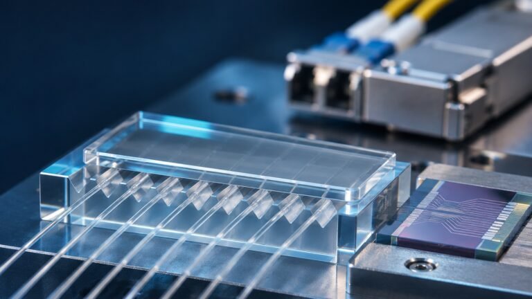



High-speed optical modules bring chips, fibers and electrical circuits into a compact package. Glass components may be small, but their dimensions and surfaces can help establish the mechanical references used during assembly. Glass does not set a module's data rate; its contribution is to make an optical interface manufacturable, alignable and inspectable.
Scope. This guide concerns glass parts and their interfaces. Insertion loss and lifetime reliability are properties of the assembled, tested optical system, not of a glass sheet by itself.
1. Where does glass enter an optical module?
Depending on the design, glass can be used as a fiber-array V-groove substrate or lid, a precision window, a protective cover or a flat substrate for another optical component. A covered fiber array unit (FAU) may locate fibers against grooves and a lid before adhesive cure and end-face finishing. Other assemblies, including lidless arrays, use different constraints.

The component drawing should specify whether a dimension applies to the empty glass part or the finished fiber assembly. Groove pitch, fiber-core pitch and core height are different quantities. For the detailed FAU geometry and coupling discussion, see our FAU and CPO engineering guide.
2. Material selection starts with the full assembly
Select a stated glass grade against the working wavelength, temperature range, available thickness, required surface and processing route. Compare its expansion with the fiber, chip carrier and adhesive system; a low expansion coefficient alone does not guarantee a stable joint. Any numeric property must be taken from the specified grade's data sheet at its stated test conditions.
A material used for a window may prioritize transmission and surface quality; a mechanical lid may prioritize dimensional stability, edge integrity and bonding compatibility. Material choice and the acceptance plan should therefore be reviewed together. Our glass material selection guide covers the broader selection process.

3. Specify the geometry that the assembly actually uses
Length, width and nominal thickness are only the starting dimensions. Thickness tolerance defines the permitted thickness range. Total thickness variation (TTV) is the difference between the thickest and thinnest measured points in a defined area. Flatness describes the shape of a specified functional surface. Parallelism describes the relative orientation of opposite surfaces. One value does not stand in for another.

For narrow lids, edge chips and subsurface damage can matter during handling, bonding and subsequent finishing. Define the permitted edge condition rather than using an ambiguous phrase such as “optical quality.” Surface roughness, scratches, particles and cleanliness likewise need separate inspection criteria. See the glass geometry and polishing guide for measurement concepts.
4. Processing and handling can change the usable part
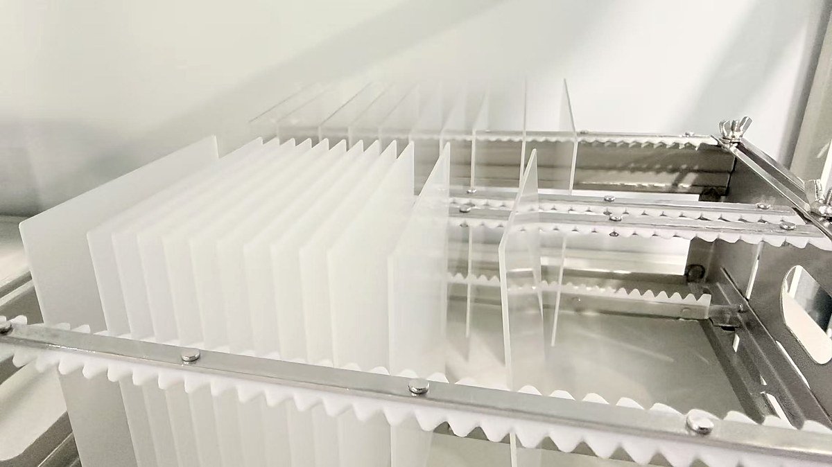
Cutting, edge finishing, cleaning, packaging and transport each affect a different risk. A part can meet its nominal dimension yet fail assembly because a functional edge is chipped, a bonding face is contaminated or a thin sheet has been scratched during transfer. Process planning should identify which surfaces may be touched, supported or protected.

5. Control the interface, not just the individual part
In a fiber interface, final position also depends on fiber geometry, adhesive dispense and cure, assembly force, thermal mismatch, end-face preparation and cleanliness. Errors have directions and correlations. Adding every maximum tolerance as a single scalar does not predict actual optical loss. Establish an assembly tolerance budget, then validate it with metrology and optical tests.
Do not treat a calculation of ideal Gaussian-mode overlap as a product guarantee. The previous FAU guide gives the correct idealized lateral-offset model and states its limits; the module must be tested at its real wavelength and operating conditions.
6. What should a drawing and RFQ include?
Provide the material grade or selection criteria, finished dimensions, functional datum, thickness tolerance, TTV and flatness if needed, surface and edge requirements, cleaning and packaging instructions, drawing revision, quantity and use conditions. For a fiber-array interface, also identify the groove profile, pitch, fiber count and which measurements apply before or after assembly.
Acceptance should name the measurement area, instrument or method, sampling plan and responsible assembly stage. A sample passing inspection is useful evidence, but batch capability must be established separately. LIGHTING GLASS can review the glass-part drawing and proposed inspection route; send your drawing for review.