

Co-packaged optics (CPO) brings an optical engine close to a switching chip to shorten the high-speed electrical path. The optical path still has to connect to fibers. That transition makes the geometry of a small fiber-array unit (FAU) consequential: the glass substrate and lid establish mechanical references, while fiber geometry, adhesive and assembly determine the final optical-axis position.
Engineering boundary. A glass part does not set a transceiver's data rate. Its geometry and material compatibility can contribute to alignment error, coupling loss and reliability; the assembled optical interface must be tested.
1. Where CPO meets the fiber array
For edge coupling, light enters or leaves a waveguide at the chip facet. For grating coupling, a surface grating redirects the optical field. The two interfaces impose different approach angles, facet positions and assembly clearances. A drawing for one configuration cannot be reused for the other without optical and mechanical review.
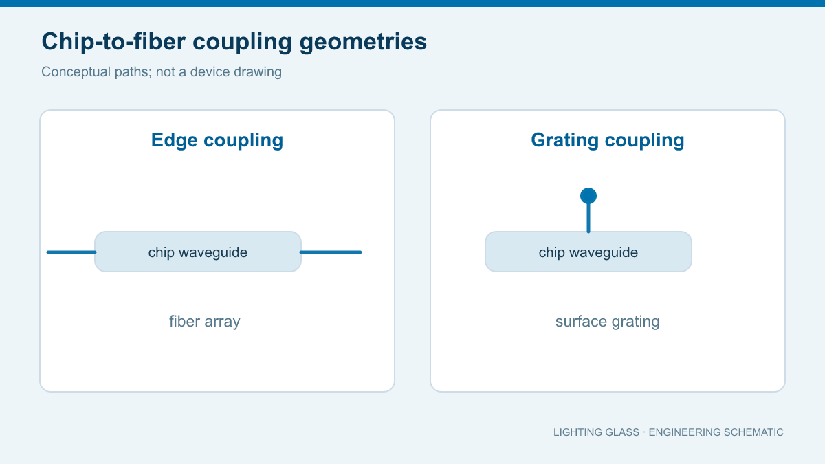
In CPO, channel density and restricted access can make repeatable passive positioning especially useful. The optical engine designer must still define the allowable insertion loss, return loss, service temperature and rework strategy for the complete assembly.
2. What is inside an FAU?
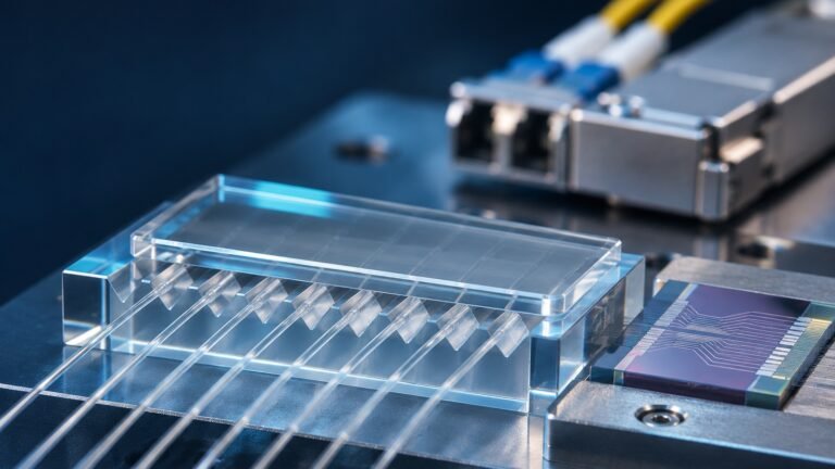
“Fiber array” (FA) describes fibers arranged at defined positions. “Fiber array unit” (FAU) usually means an assembled array ready for subsequent integration. A covered unit may contain a V-groove substrate, fibers, glass lid, adhesive and a prepared end face. Lidless and other constructions also exist.
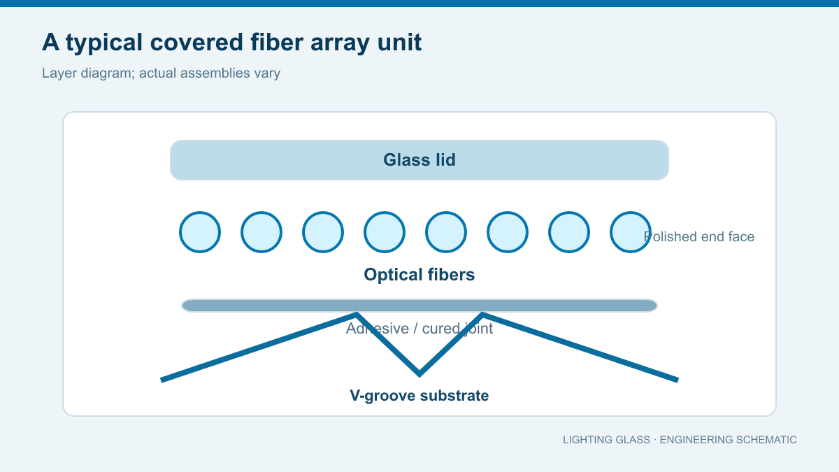

The V-groove provides a geometric reference for the fiber cladding; the lid constrains the fibers from above. Adhesive dispensing, cure and end-face finishing then become part of the assembly process. Groove pitch alone cannot prove core pitch: cladding diameter and core-to-cladding concentricity also matter. For more on groove geometry and inspection, see our V-groove substrate guide.
3. How a V-groove and lid locate the fiber
Groove pitch is the designed spacing between adjacent grooves. Core pitch is the spacing between optical cores in the finished array. Core height is the core center's distance from a stated datum. These must be distinguished on the drawing and in the inspection plan.
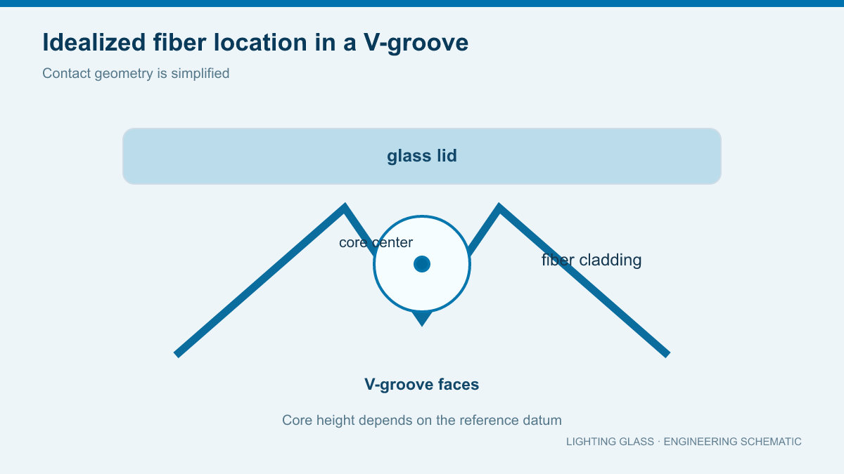
Groove angle and depth, cladding diameter, concentricity, lid shape and assembly pressure all affect the final core location. State which surface is the datum and whether each tolerance applies to the empty glass part or the assembled FAU.
4. Why a micrometre of offset may matter
A simple Gaussian-mode overlap model illustrates sensitivity to lateral displacement. For two identical, perfectly aligned mode shapes except for transverse offset Δ, with mode-field radius w and MFD = 2w, coupling efficiency is η = exp[−(Δ/w)²]. The additional loss is L = −10 log₁₀η dB. This is a model assumption, not a glass-part acceptance value.
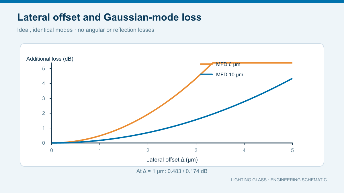
At Δ = 1 µm, the model gives approximately 0.174 dB for MFD = 10 µm and 0.483 dB for MFD = 6 µm. Actual insertion loss also depends on wavelength, chip mode shape, angular alignment, end-face condition, adhesive and temperature. Specify the optical loss budget at system level and verify it on the assembled device.
5. Glass-lid specifications beyond length and width
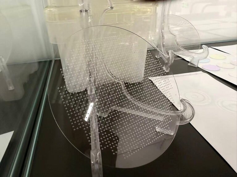
Thickness tolerance defines the allowable finished thickness. TTV is the difference between the maximum and minimum thickness within a defined area. Flatness describes departure of a functional surface from an ideal plane; parallelism concerns the relative orientation of opposing surfaces. They are separate requirements and need a measurement area and datum.
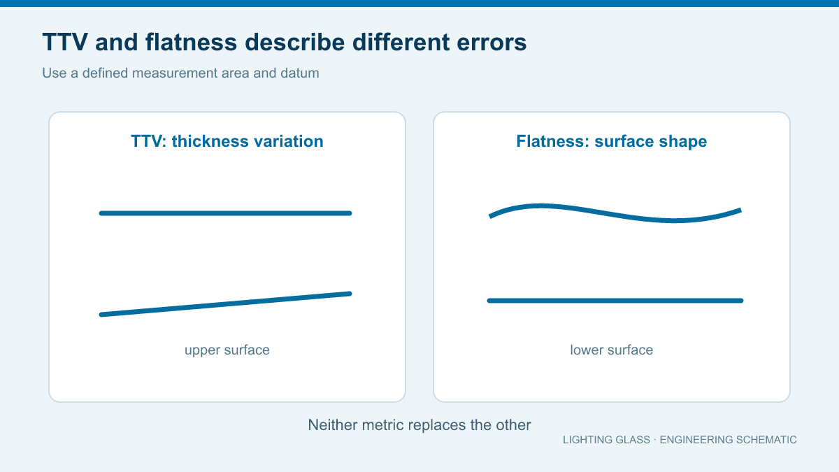
Surface roughness Ra and scratch-dig address different scales of surface condition. Edge chipping and subsurface damage may matter when narrow strips or thin lids are handled, bonded or finished. Cleanliness should be stated together with the intended bond or optical interface, not as an undefined “optical grade.” Our glass geometry guide explains TTV, flatness and parallelism in more detail.

6. Material selection and thermal compatibility
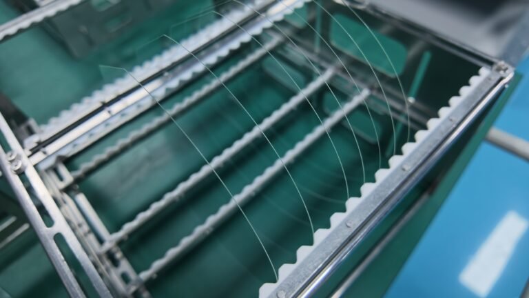
Choose the glass by its specified material grade, available thickness, dimensional stability, machining response and compatibility with the assembly's adhesive and thermal cycle. A lower coefficient of thermal expansion is not automatically better: the relative expansion of glass, fiber, chip and adhesive governs stress and positional drift. Request the source material data sheet for any numeric property and evaluate the actual temperature range.
Material selection and processing route should be reviewed together. Cutting, groove formation, edge finishing, cleaning and packaging can each affect a different functional surface. Generic values from another glass grade should not be copied onto a customer's drawing.
7. Build an assembly tolerance budget
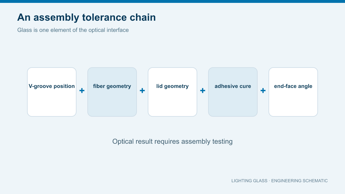
A useful tolerance budget tracks groove position and form, fiber cladding and core eccentricity, lid shape, adhesive cure, thermal mismatch, and end-face angle and cleanliness. These contributions have different directions and correlations; simply adding every maximum tolerance can misrepresent the actual process. Use sample metrology, assembly trials and optical tests to validate the budget.
A dimensionally conforming glass piece is not proof that the assembled FAU meets its optical or reliability requirement.
8. Turn the optical need into an inspectable drawing
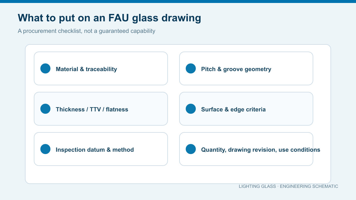
Provide the material grade and traceability requirement, fiber count and pitch, groove profile and reference datum, finished dimensions, thickness tolerance, TTV, flatness, edge and surface criteria, bonding surfaces, cleaning condition, drawing revision and quantity. Mark which dimensions apply before assembly and which results will be accepted after assembly.
LIGHTING GLASS can review customer drawings for glass-material selection and precision glass processing. Send your drawing, usage conditions and acceptance criteria through our contact and RFQ page so the material, process and inspection route can be assessed together.