


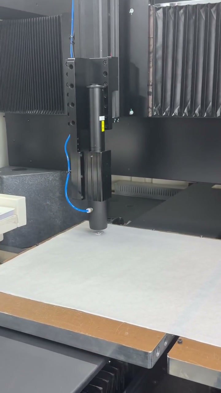
Glass chipping begins when a machining or separation operation creates a crack that reaches a free surface or edge. The visible chip is only part of the problem: a damaged edge can also contain cracks that are difficult to see. A useful cutting specification therefore connects the part function with support, process sequence, edge finishing and inspection, rather than simply asking for a smoother-looking cut.
Why edges chip during cutting
Glass responds differently from a ductile metal. Local tool loading, vibration, unsupported exit edges and existing damage can initiate brittle fracture. In scoring and separation, the controlled crack must follow the intended path. In abrasive cutting, individual abrasive contacts remove material but may leave edge damage. In laser processing, the relevant risks depend strongly on the laser process and material response; a laser label alone does not establish a damage-free edge.
Thin sections, small features, closely spaced holes and sharp corners can change local support and stress. Material grade and incoming surface condition also matter. An unchanged tool program is not evidence that borosilicate, aluminosilicate and fused silica will produce identical results.
Select a route around the finished edge
| Route | Potential advantage | Issue to evaluate |
|---|---|---|
| Score and separate | Useful for appropriate straight cuts in compatible stock. | Crack path, edge profile and whether subsequent finishing is necessary. |
| Abrasive sawing or machining | Supports controlled removal and many part geometries. | Tool wear, support, coolant, entry and exit damage. |
| Laser-based separation or ablation | Can suit specific shapes and fine features. | Process-specific damage, taper, debris and downstream edge requirements. |
Review precision glass cutting and edge grinding and beveling as one sequence. A nominally correct cut size may be insufficient if later edge finishing removes a required reference or leaves too little dimensional allowance.
Specify chip size, location and the inspected region
Define the edge and corner zones, the permitted defect size and the inspection method. A maximum chip depth into a functional region is different from a limit on the length of an edge defect. Specify both when necessary. State whether the measurement occurs before or after chamfering and which edges are functional datums, seal locations or exposed handling surfaces.
Optical surface imperfections and mechanical edge damage may need separate criteria. A scratch-dig designation does not replace an edge-chip requirement. For an optical clear aperture, identify the excluded perimeter explicitly rather than assuming every visible chip is either harmless or unacceptable.
Qualification should reproduce the real geometry
Test the actual material, thickness, feature spacing and edge treatment. Inspect representative entry and exit regions, corners and narrow ligaments. Compare first and later parts in a run to investigate wear or process drift. If strength or reliability is critical, agree a suitable qualification method; passing a visual chip inspection does not prove freedom from subsurface damage.
Check dimensions after the complete cutting, finishing and cleaning sequence. Fixtures, temporary adhesives and coolant residues can affect both geometry and later cleaning. The cleaning guide explains why these decisions belong in the process plan.
Investigate defects systematically
Record where defects occur, how they change with tool life and whether they appear before or after cleaning. Consistent exit-edge chipping suggests a different investigation from random damage introduced during packing. Keep material, fixture and process records for the qualification lot. Avoid changing several process variables at once if the purpose is to identify the cause.
Preparing a cutting RFQ
Provide material, thickness, outline, dimensions, tolerances, quantity, critical datum edges, chip limits and finishing requirements. Identify nearby holes and narrow sections, surface protection, cleaning and packaging. Include a drawing and the intended mounting or sealing function.
Define inspectable acceptance criteria · Compare glass materials
Technical reference
ISO 10110-7:2017 addresses optical surface imperfections and includes edge-chip indications within its scope. Mechanical edge requirements should still be explicitly agreed for the particular part. This guide does not claim a universal chip-free process or production tolerance.