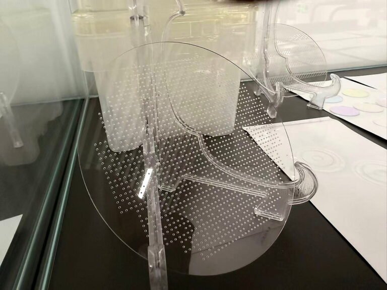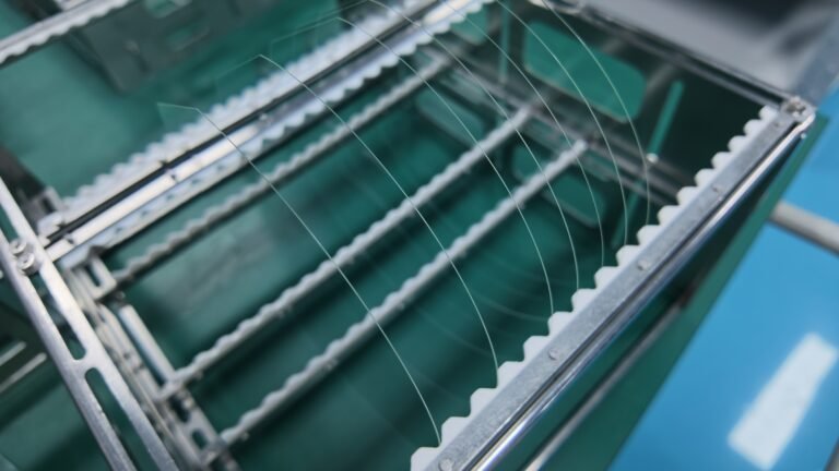


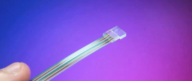
A fiber array (FA) positions multiple optical fibers at a defined pitch so they can be aligned and joined as one assembly. The V-groove glass substrate is a small part of that assembly, but its geometry establishes where each fiber sits. A mismatch in groove pitch, shape or datum position can carry through to the finished array.
This guide reorganizes the key points from our V-groove and fiber-array article for engineers and buyers specifying the glass components. It separates what can be checked on a bare substrate from optical performance that must be measured after fiber placement, bonding and end-face finishing.
How the substrate, fibers and lid work together
A typical assembly contains a V-groove base, fibers, a matching glass lid and adhesive. The grooves locate the fibers; the lid and adhesive retain their positions. The substrate drawing therefore needs to describe the fiber layout and the mating lid, not just the outside dimensions of a glass blank.
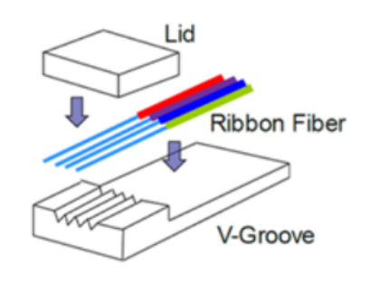
The glass component and the completed FA should have separate acceptance criteria. Groove pitch and dimensions can be inspected before assembly. Insertion loss, return loss and long-term stability depend on the complete optical path, including fiber quality, adhesive, alignment and polished end faces.
Specify the groove geometry from the fiber outward
Start with fiber cladding diameter, channel count and required center-to-center pitch. Then define the groove angle and depth, the location of the first and last channels relative to a datum, and the tolerances that matter to alignment. An attractive-looking cross-section is not enough to establish fiber-center accuracy.

| Drawing item | What to define | Why it matters |
|---|---|---|
| Fiber and channel layout | Fiber type, cladding diameter, channel count, nominal pitch and array direction | Establishes the intended fiber-center pattern. |
| Groove profile | Included angle, depth, bottom condition, straightness and surface condition | Controls how consistently fibers seat along the groove. |
| Position and datums | First-channel offset, cumulative pitch error, end position and inspection datums | Allows the substrate to be aligned and measured in the same coordinate system as the assembly. |
| Substrate and lid | Length, width, thickness, lid dimensions, flatness, parallelism and edge condition | Influences fit, handling, adhesive gap and contact during assembly. |
| Verification | Sampling plan, measurement method and acceptance limits | Makes a tolerance actionable for production and incoming inspection. |
Set numerical tolerances from the actual fiber, assembly process and optical budget. A value demonstrated on one part size or fixture should not be treated as a universal capability for every substrate design.
Choose glass and processing as one route
Quartz or fused silica, borosilicate and alkali-free glasses can be considered for V-groove components. The choice should reflect the optical package, thermal cycle, chemical exposure, adhesive or bonding route, and any mating materials. Ask for the exact grade and supply form rather than relying on a broad material name.
The manufacturing route may combine blank cutting, precision groove machining, edge finishing, grinding or polishing, cleaning and dimensional inspection. Process selection is driven by groove geometry and damage limits. In particular, the groove profile, chipped edges and residual debris should be reviewed before fibers and lid are assembled.

What optical tests can—and cannot—prove
Insertion loss (IL) compares the optical power entering and leaving a defined path. Return loss (RL) concerns reflected power. Neither number is an intrinsic property of the unassembled V-groove glass. Fiber positioning, end-face geometry, polishing, contamination, connectors and test conditions all affect the finished reading.
For that reason, an RFQ should state the test wavelength, connection method, reference procedure, channel count and acceptance criteria if IL or RL is required. Quoting one low-loss or high-return-loss figure without its measurement conditions can be misleading.
Inspect beyond the two end faces
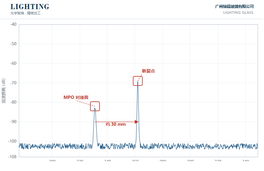
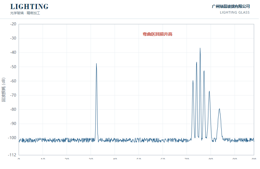
A microscope or end-face inspector can reveal visible chips, scratches and contamination at an accessible face. A red-light check can help locate some breaks or leakage. Those checks do not, by themselves, locate every internal microbend, adhesive-related stress point or concealed defect in a packaged assembly.
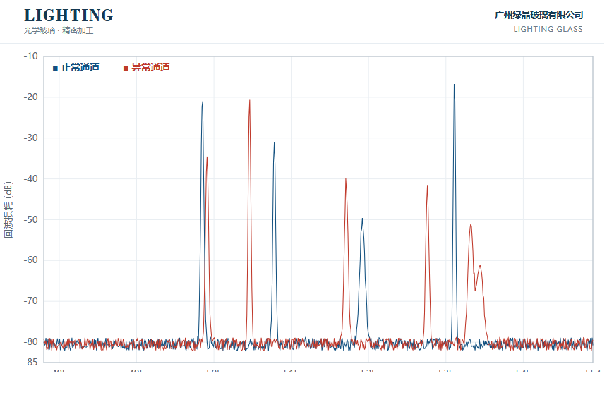
The source article also shows distributed return-loss scans along a fiber path. These examples illustrate how localized reflection features can differ between a normal and an abnormal channel, and how a suspected break or bend may appear in a scan. Interpretation depends on the instrument, calibration, path layout and test setup; the images are examples, not acceptance curves for every product.
A practical qualification sequence
- Confirm the interface: freeze the fiber, lid and substrate drawing revisions, the assembly datums and the required channel layout.
- Approve a representative sample: inspect groove profile, pitch, cumulative position, substrate geometry, edge condition and cleanliness using agreed methods.
- Build and test the assembly: place fibers, bond the lid, finish the end face and measure the optical criteria under documented conditions.
- Carry the controls into production: agree sampling, traceability, cleaning, packaging and how nonconforming parts will be handled.
Frequently asked questions
Is groove pitch alone enough to specify a fiber array substrate?
No. Fiber diameter, groove angle and depth, cumulative channel position, substrate datums, lid fit and inspection method also determine whether the component will assemble as intended.
Can a glass substrate guarantee a target insertion loss?
No. The substrate contributes to fiber positioning, but insertion loss is measured on the completed optical path. Include assembly and test conditions when setting a loss target.
How should an internal defect be investigated?
Begin with accessible end-face and visual checks. Where the application warrants it, use a suitable distributed optical measurement to investigate reflections along the assembled path, and interpret the trace against the known layout.
Send a drawing for a V-groove glass review
For a useful quotation, provide the glass grade or operating conditions, fiber type and cladding diameter, channel count, pitch, groove profile, substrate and lid dimensions, critical tolerances, quantity and intended inspection criteria. State whether you need separate glass components or an assembled and optically tested fiber array.
Glass lids for V-groove fiber arrays · Precision glass cutting · Glass polishing · Discuss your project
Image source: the original WeChat article. The diagrams and scan examples illustrate the concepts discussed here; final specifications and acceptance limits must be confirmed for the actual drawing and assembly.