LIGHTINGOptical Glass · Precision Processing
Contact Us中文 / English⌕
V-groove cover glass case study
CASE STUDY · Precision Structural Glass

V-Groove Cover Glass Processing Case Study

For optical communication, sensing and precision assembly projects, the process route for V-groove cover glass is organised around material, groove machining, edge quality, cleaning and inspection.
Project Overview

The complete route from material confirmation to finished-part delivery

A V-groove cover glass must not only meet outline dimensions but also control groove width, groove depth, groove angle, end chipping and assembly datums. In this case study we follow the drawing requirements and plan cutting, precision forming, edge treatment, cleaning and inspection starting from material confirmation.

Typical materials
Fused quartz, borosilicate glass or a specified optical glass
Main operations
Precision cutting, groove machining, edge grinding, cleaning, inspection
Control focus
Groove dimensions, position datum, chipping, surface cleanliness
Applications
Optical communication components, sensors, precision assembly
Discuss a Similar Project
ENGINEERING GUIDE

Deriving the glass structure from fibre position relationships

A V-groove cover glass can serve clamping, positioning, protection, packaging or transparent viewing functions. It may be a flat thin sheet or carry grooves, steps or holes. The key is not machining a groove in isolation, but making the material, fibre core position, groove geometry, adhesive layer and assembly datums jointly satisfy the coupling and packaging requirements.

Applications

Where it can be used

  • Fibre array units (FAU) and multi-channel fibre positioning structures
  • PLC splitters, AWG, couplers and optical module packaging
  • Fibre optic sensors, lasers and detector assemblies
  • Parallel positioning of micro-tubes, capillaries or fine wires
  • Precision assemblies requiring transparent clamping, retention or viewing
Material Selection Logic

Why glass

Glass offers electrical insulation, ageing resistance, dimensional stability and precision machinability. Fused quartz suits assemblies needing low thermal expansion and higher optical requirements; borosilicate glass balances machinability, thermal stability and cost; alkali-free thin glass suits microstructures sensitive to thickness consistency, surface and ionic contamination.

Material Selection

Common materials and their applications

MaterialApplicationsSelection focus
Fused quartz / JGS1Low thermal expansion, near-infrared or UV optical pathsConfirm operating wavelength, hydroxyl/purity, internal quality and surface grade
BOROFLOAT® 33Standard optical communication cover plates, support plates and bars/lidsCTE 3.25 × 10⁻⁶ K⁻¹ (20–300 °C); confirm adhesive bonding and thermal cycling
EAGLE XG® / alkali-free glassThin cover plates, microelectronics and low-alkali structuresFocus on thin-sheet support, edge strength and downstream thin-film processes
Typical Parameters

Common enquiry parameters

ItemCommon starting points or wordingEngineering notes
Cover plate thicknessCommonly 0.20–1.10 mm; other values assessed by materialAffects assembly height, stiffness, adhesive layer and breakage risk
Fibre pitchCommonly 127, 250, 500 μm and othersMust be confirmed against fibre diameter, channel count and centre height
Outline toleranceNormally discussed from ±0.05 mm; precision small parts can be assessed to ±0.03 mmDepends on length, thickness, material and quantity
Minimum widthAssessable to 1 mmLength, thickness and handling method must be confirmed together
Edge chippingPrecision small parts assessable to <0.10 mmTighter zone-specific standards can be set for fibre, adhesive seal and corner areas
Groove width / groove depth / groove angleAccording to fibre and assembly designDo not substitute default groove dimensions for component calculations
Surface qualityNon-optical faces by appearance; optical faces commonly discussed from 60/40 or 40/20State the scratch/dig standard, effective aperture and illumination conditions
Structure and Function

What it usually needs to look like

Common forms include flat cover strips, V-groove cover plates, multi-groove cover plates, stepped retaining cover plates, cover plates with viewing windows or adhesive dispensing holes, and bars/lids that mate with silicon, quartz or glass V-groove bases.

  • Stabilise fibre position and array pitch
  • Limit assembly height and adhesive layer thickness
  • Protect fibres, chips and the adhesive layer
  • Provide transparent viewing or optical path windows where required
Performance Requirements

Performance items recommended for confirmation

  • Thermal expansion and temperature stability matched to the assembly
  • Stable thickness, parallelism, groove geometry and pitch
  • Low chipping, few micro-cracks and good edge integrity in functional areas
  • Transmission, surface quality and low scattering in optical path areas
  • Compatibility with adhesives, cleaning media and packaging temperature
  • Low particles, no obvious residue, water marks or contact contamination
Preparing Your Enquiry

Please provide in the drawing or enquiry

Material grade, 2D/3D drawing, cover plate thickness, fibre diameter and pitch, channel count, groove dimensions, assembly datums, functional faces, permitted chipping, surface grade, bonding or packaging temperature, quantity and packaging method.

The parameters above are for preliminary material and process selection and do not constitute a uniform guarantee for all dimensions, thicknesses and materials. Final specifications, measurement methods and delivery standards are governed by the drawing, samples and order documents confirmed by both parties.

01

Drawing and material confirmation

Confirm groove width, groove depth, groove angle, end structure, datum faces and material grade, and identify thin walls, sharp corners and machining interference in advance.

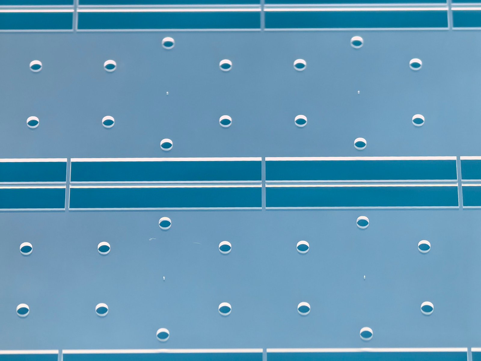
V-groove cover glass processing and material preparationV-groove cover glass processing inspection
02

Outline and groove machining

Establish a stable outline and positioning datum first, then complete precision V-groove forming; CNC, grinding or a combined process is assessed according to the structure.

03

Edge and surface protection

Treat sharp edges, tiny chips and local stress concentration, and protect functional faces during handling to avoid scratches and recontamination.

04

Cleaning, inspection and delivery

Check groove geometry, position, outline, edges and appearance against the drawing, then complete cleaning, separated packaging and batch delivery.

Start material selection and processing requirements from the same drawing

Send the drawing and key acceptance items and we will assess the project together with the material and process route.