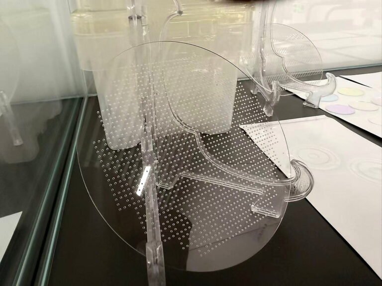



Through-hole: a TGV opens on both faces; a top view alone cannot prove completion.
Geometry: specify entry, exit and minimum waist diameters separately.
Inspection: agree on methods, datums and acceptance criteria before production.
In precision glass micro-hole manufacturing, a hole that appears circular from above may still be unacceptable. It could stop before the bottom surface, have an undersized waist, exhibit excessive taper, contain edge damage, or miss its required location. For through-glass vias (TGVs), inspecting only the top opening is not enough.
This guide explains how glass thickness, hole diameter, laser-processing strategy and subsequent etching affect micro-hole geometry. It also shows how optical inspection helps identify irregular hole edges, why wafer and panel geometry must be controlled, and which specifications engineers should provide when ordering custom drilled glass substrates.
Our practical focus is borosilicate glass, particularly BF33, along with other specialty glass materials evaluated on a project-by-project basis. The images are from actual sample or inspection work; they illustrate engineering concerns and are not standalone certifications of a finished lot.
What Makes a Through-Glass Via Different From a Blind Hole?
A through-glass via (TGV) is an opening that extends completely through the thickness of a glass substrate. In semiconductor packaging, the via can subsequently be incorporated into a metallized interconnect structure. A bare, unmetalized hole is the fabricated glass feature, not yet an electrically functional interconnect.
A blind hole has a defined depth but does not open through the opposite face. Blind holes and cavities are valid structures when the drawing calls for them. If the purchase specification explicitly requires a through-hole, however, an incomplete opening is a nonconformance that must be evaluated for rework or rejection.
Why it matters: a nearly opened hole can resemble a complete one in a top-view microscope image. Through-penetration requires appropriate inspection, potentially including transmitted illumination, inspection from both faces, suitable non-destructive 3D metrology or sectioning during process qualification.
Why Hole Diameter, Glass Thickness and Waist Geometry Matter
The nominal drawing diameter is only one dimension of a micro-hole. Depending on the fabrication route, the entry diameter, exit diameter and narrowest internal diameter may differ.
- Entry diameter (D_top): opening measured at the laser-entry or designated top face.
- Exit diameter (D_bottom): opening at the opposite glass face.
- Waist diameter (D_min): smallest internal diameter along the hole depth.
- Taper: change of hole diameter across thickness; define the method and reference diameter rather than quoting an isolated angle.
- Circularity / roundness: deviation of an actual hole perimeter from the specified circle, using an agreed calculation and measurement plane.
- Position and pitch: hole center relative to datums and neighboring holes.
Thicker glass, smaller target openings and greater hole aspect ratios may make it harder to control penetration, sidewall profile and processing consistency. The outcome also depends on laser focus, energy delivery, scan strategy, glass composition and etching conditions.
A larger specified hole may be easier to keep circular in some established process windows. That does not mean larger holes are intrinsically rounder, or that thicker glass always produces a larger minimum waist diameter. These relationships require actual process trials and section-profile measurements.


Define Diameter Tolerances on the Correct Measurement Plane
A request for a nominal hole diameter and a tolerance is incomplete unless it identifies what is measured: top opening, bottom opening, minimum waist, mean fitted diameter or another specified geometry. The inspection standard, datum reference and measurement method must also be agreed.
For arrays, dimensional acceptance may separately include hole-to-hole uniformity, pitch, position error and edge-to-hole distance. Roundness should not be confused with diameter tolerance or true-position tolerance.
Laser Processing Routes for Glass Micro-Holes
Direct Laser Ablation
In direct laser ablation, the laser removes glass by a controlled material-removal mechanism. The process can be suitable for selected micro-holes and contours, but the chosen settings affect entrance and exit quality, taper, re-deposition and the risk of thermal or mechanical damage. Cleaning and inspection may be necessary before downstream coating or assembly.
Laser Modification Followed by Selective Etching
A different route uses laser exposure to create locally modified glass regions and subsequent selective wet etching to remove those regions and develop the final geometry. Such processing can be considered for fine holes and arrays; the usable window is strongly material- and thickness-dependent.
A process may use a point-like modified region for a small hole or a scanned circular contour for a larger opening. These are different toolpath concepts, not a universal threshold defined by one diameter. The initial laser-affected feature should never be reported as the finished hole diameter.
Extending an opening by etching can take additional process time and require more chemical bath management or treatment. Cost estimates may therefore depend on material, panel thickness, hole count, diameter, pitch, shape requirements, etch route, inspection scope and qualification yield. It is not technically defensible to quote cost from diameter alone.
Common TGV and Micro-Hole Defects
Incomplete Through-Penetration
When a through-hole is required, an opening that ends within the glass cannot be accepted as a completed TGV. A front-face view alone may not establish whether the opposite face is open. The acceptance plan should specify how complete penetration is verified.
Irregular Hole Perimeters and Poor Circularity
An apparently uneven perimeter may result from locally nonuniform material removal, process instability, chipping or other defects. The correct diagnosis requires calibrated imaging and may require additional views; a photograph alone cannot establish whether the cause is laser energy, etching or pre-existing glass damage.
Compare hole profiles against an agreed geometric definition and defect criteria. A defect photograph may show why an inspection is needed, but it must not be treated as a quantitative circularity report without measurement evidence.

Taper, Constriction and Waist Deviation
A TGV can have an acceptable top opening while its bottom or internal waist is too narrow for the application. Inspection may require measurement from both faces and a method capable of resolving the internal profile, particularly for high-aspect-ratio features.
Cracks, Chipping and Residual Contamination
Local edge chips, cracks, redeposited debris or etching residues may impair strength, cleaning, bonding or subsequent metallization. The inspection plan should define acceptable edge zones, contamination criteria and downstream process needs.
How Do Engineers Inspect Glass Holes and Panels?
Inspection should be designed around what the fabricated glass must do next. Optical imaging can establish visible perimeter geometry, array layout and certain surface defects, but does not by itself prove internal hole-wall quality or penetration.
For a complete micro-hole inspection plan, possible measurement tasks include:
| Inspection item | Engineering question | Possible verification approach |
|---|---|---|
| Through-hole completion | Is the opposite side open? | Opposite-face/transmission inspection or qualified 3D/sectional method |
| Top and bottom diameters | Are both openings within their specified limits? | Calibrated optical measurement on each face |
| Waist and taper | Does internal geometry meet the required profile? | Validated 3D/sectional or suitable through-hole metrology |
| Circularity | How far does the perimeter deviate from a circle? | Calibrated perimeter data with agreed fit method |
| Position and pitch | Are hole centers correctly located? | Referenced optical/CMM-style coordinate inspection |
| Edge defects | Are chips and cracks acceptable? | Microscope inspection with agreed criteria |
| Panel bow/warp | Will the panel meet handling and process requirements? | Dedicated geometry metrology with defined support conditions |
Wafer or panel bow and warp matter because global deformation can affect focusing, registration, handling and downstream assembly. However, an optical comparator photograph alone is not proof of a measured bow or warp value. That requires the correct instrument setup, method and actual recorded results.


What Changes When the Glass Substrate Becomes Larger?
Large substrates add challenges beyond a single hole. The manufacturing and inspection plan may need to consider overall panel dimensions, thickness, warp/bow, fixturing and support, thermal stability, hole positions over a broad area, handling and breakage risk.
One user-supplied example is a 510 × 515 × 0.5 mm glass panel. The photograph illustrates a large, thin substrate being handled in a workshop setting. It should not be interpreted as a certified measurement of panel-wide microhole accuracy or a guaranteed production specification.

For large-format glass micro-hole projects, the drawing should state both local feature tolerances and global panel requirements. A hole can be locally acceptable but unusable in assembly if its position relative to the entire panel datum system is incorrect.
Which Glass Materials Can Be Considered for Micro-Hole Drilling?
Material composition affects laser interaction, cracking susceptibility, etch response, surface condition and available processing windows. As a result, the correct machining route must be validated for each grade and thickness.
| Glass family | Engineering relevance | Processing review required |
|---|---|---|
| BF33 borosilicate glass | A practical focus for the company's existing machining experience | Thickness, laser/etch response, TGV profile, dimensional acceptance |
| Fused silica / fused quartz | Optical, laboratory and selected high-stability applications | Laser absorption, etch conditions, crack prevention, cost |
| Alkali-free boro-aluminosilicate | Electronic and semiconductor-related substrates | Grade-specific processing, edge quality, thickness and cleanliness |
| Aluminosilicate glass | Select electronic and precision technical components | Process energy, composition, residual stress and hole-wall quality |
| Thin technical borosilicate and selected optical glass | Microfluidics, sensing and precision substrates | Handling, thermal response, etching and defect criteria |
This is an evaluation list, not a guarantee that every glass family supports the same minimum diameter, depth, tolerances or equipment setup.
How to Request a Quote for Custom Glass TGV or Micro-Holes
Buyers and engineers should send enough information to review both feasibility and inspection. Recommended RFQ items:
- Exact glass grade or target material properties.
- Glass sheet, wafer or panel dimensions and thickness.
- Through-hole, blind-hole, recess or hole-array designation.
- Top, bottom and minimum waist diameters, where relevant.
- Hole count, pattern, pitch, position datums and distance to edge.
- Diameter tolerance, circularity, taper and allowed chipping/cracking.
- Required material and surface condition before drilling.
- Subsequent cleaning, bonding, coating or metallization process.
- Inspection method, sampling plan, reporting and acceptance criteria.
- Sample quantity, production quantity, drawing and delivery schedule.
The drilling process and target specifications can then be reviewed together. In development work, initial sample qualification is often important before any lot-wide acceptance commitment is made.
Material Supply and Precision Glass Micro-Hole Processing
Guangzhou Lighting Glass Co., Ltd. supplies technical glass materials and supports build-to-print precision glass processing. BF33 borosilicate glass is a key material in our practical glass micro-hole development experience. Other selected glass compositions may also be evaluated using the customer's exact dimensions and downstream needs.
Projects can begin with raw glass sheet procurement or with a drawing for custom glass substrates, hole arrays, laser drilling, precision processing, grinding, polishing and inspection. Feature feasibility, process route, surface requirements and acceptance criteria are reviewed before any manufacturing commitment.
Contact our team for material supply or custom glass micro-hole processing. Include your material, drawing, thickness, top/bottom hole diameters, pitch, tolerances, quantity and any subsequent bonding or metallization requirements.
Frequently Asked Questions
Is a blind hole automatically a rejected TGV?
Only when the approved drawing requires a fully through opening. Blind holes can be intentional features in other designs. The evaluation of an unintentional blind hole depends on whether qualified rework is feasible and allowed.
Are larger glass micro-holes always rounder?
No. Some established process windows may control larger holes more readily, but circularity depends on material, thickness, toolpath, laser settings, etch route and metrology.
Why is glass thickness relevant to the hole waist?
Thickness changes the hole aspect ratio and may influence how energy, modifications and etchants develop the internal profile. The minimum waist diameter must be measured; it cannot be assumed from the top opening or thickness alone.
Can top-view optical images prove a TGV has fully opened?
Not reliably by themselves. Inspection from the back side, transmission or suitable internal-geometry methods may be required, depending on the specified acceptance criteria.
Can borosilicate glass, fused silica and aluminosilicate all be drilled identically?
No. Glass composition and thickness change the feasible laser and etch settings, surface damage risk and inspection plan. Feasibility should be reviewed per grade.
Is a drilled glass panel a complete TGV interposer?
Not necessarily. A drilled glass substrate may be an intermediate component. A fully functional electrical interconnect can additionally require conductive filling or metallization, redistribution layers and package-level qualification performed by the appropriate provider.
See more in our Technical Knowledge center.
Discuss Your Glass Drilling Project
Send your drawing, material grade, glass thickness, hole geometry, array pitch, quantity and inspection requirements. We will review feasibility before making any process commitment.
Contact: Manager Chen (Chen Chuangfeng)
Phone / WeChat: +86 13539645045
Email: jerry-ton@lightingglass.cn