LIGHTINGOptical Glass · Precision Processing
Contact UsChinese / English⌕
Glass strip case study
CASE STUDY · Narrow Strips and Bar/Lid Processing

Glass Strip Processing Case Study

For narrow strips, bars, lids and elongated glass parts, we focus on width, length, chipping, parallelism and batch consistency.
Project Overview

The complete route from material confirmation to finished-part delivery

The dimensions of a glass strip look simple, but the narrow width-to-length ratio, thin-sheet handling, cutting chipping and batch consistency significantly affect later lamination, packaging or optical assembly. Projects should design the processing and inspection plan starting from the source sheet, layout direction and datum edge.

Typical materials
EAGLE XG®, BOROFLOAT® 33, fused quartz and others
Main operations
Precision cutting, edge grinding, cleaning, dimensional inspection
Control focus
Width, length, parallelism, chipping and batch consistency
Applications
Optical communication bars/lids, sensor packaging, precision spacers
Discuss a Similar Project
ENGINEERING GUIDE

The difficulty in narrow strip processing lies in edges and lot-to-lot consistency

Bars, Lids and Spacers are usually narrow and produced in high volume, with a long edge used as the assembly reference. Cutting skew, edge chipping or corner damage accumulate into positional deviation during volume assembly, and thin strips are also prone to breaking during cleaning and handling.

Applications

Where it can be used

  • Bars, Lids, window strips and V-groove cover strips in optical communication devices
  • Cover strips and spacer strips for sensors, MEMS and microelectronic packaging
  • Slit plates, light-shielding strips and transparent support strips in optical systems
  • Precision shims, insulating spacers and locating strips
  • Long glass parts in laboratory equipment, microfluidics and small structures
Material Selection Logic

Why glass

Glass bars and strips can simultaneously provide electrical insulation, transparent viewing, stable spacing, sealing boundaries and thermal matching. Compared with polymers they usually offer better dimensional stability and heat resistance, but brittleness, edges and assembly stress must be controlled.

Material Selection

Common materials and their applications

MaterialApplicationsSelection focus
BOROFLOAT® 33General Bar/Lid, sensor cover strips and shimsLow expansion, wide specification range, good cutting and polishing compatibility
EAGLE XG®Thin, low-alkali strips with a high-quality pristine surfaceFocus on protecting thin plates and edges
Fused quartz / JGS1Strips for optical paths, high temperature, low CTE or high purityConfirm the band, material grade and subsurface damage
Aluminosilicate GlassThin cover strips requiring higher mechanical reliabilityConfirm the strengthening sequence and edge quality
Typical Parameters

Common enquiry parameters

ItemCommon starting points or wordingEngineering notes
ThicknessCommonly 0.10-3.00 mmMust be considered with stiffness and handling method
WidthCommonly 1-20 mm; minimum evaluable down to 1 mmRelated to thickness, length and handling
LengthCan range from a few millimetres to several hundred millimetresThe greater the length, the more straightness and parallelism matter
Width/length toleranceGenerally discussed from ±0.05 mm; precision parts can be evaluated to ±0.03 mmThe reference and inspection method must be specified
Edge chippingPrecision small parts assessable to <0.10 mmFunctional and non-functional edges can be graded separately
End faceCut, ground or polished end facesWhere in the optical path, the angle and surface quality are specified separately
Structure and Function

What it usually needs to look like

Commonly rectangular Bars, narrow Lids, transparent Spacers, strips polished at both ends, locating strips with holes or notches, profiled strips with steps/slots, and dual-function strips ground on one face and polished on the other.

  • Protect chips, optical fibers, adhesive layers or microstructures
  • Control assembly gaps and device height
  • Serve as a transparent window, narrow optical path or optical support
  • Provide insulating isolation and a precision locating reference
Performance Requirements

Performance items recommended for confirmation

  • Consistency of width, length, parallelism and straightness
  • End face angle and surface condition
  • Low chipping, low micro-cracking and stable corners
  • Thickness, A/B faces and functional area identification
  • Compatibility with volume pick-and-place, cleaning and segregated packaging
Preparing Your Enquiry

Please provide in the drawing or enquiry

Material, length/width/thickness, key reference, width/length/parallelism tolerance, end face condition, chamfer, allowable chipping, A/B faces, functional area, quantity, arrangement and packaging method.

The parameters above are for preliminary material and process selection and do not constitute a uniform guarantee for all dimensions, thicknesses and materials. Final specifications, measurement methods and delivery standards are governed by the drawing, samples and order documents confirmed by both parties.

01

Layout and datum design

Plan the layout from source sheet size, material direction and part quantity, and define the critical datum edge.

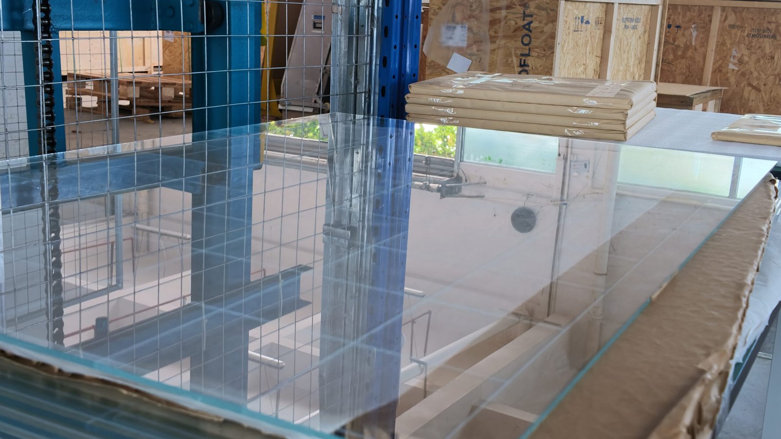
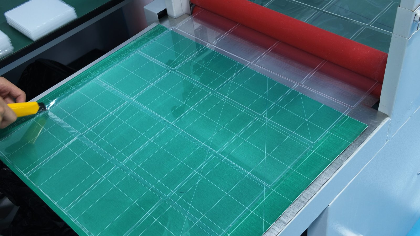
Glass strip processing and material preparationGlass strip processing inspection
02

Precision strip cutting

Control the cutting path, support method and process cycle to reduce narrow-strip deformation and edge chipping.

03

Edge dressing and handling

Edge grinding or chamfering is carried out per assembly requirements, with handling and separation methods suited to thin sheets.

04

Batch dimensional and appearance inspection

Check width, length, edges and surface, pay attention to consistency within the batch and complete clean packaging.

Start material selection and processing requirements from the same drawing

Send the drawing and key acceptance items and we will assess the project together with the material and process route.