


B270 Superwhite Glass Precision Processing: Cutting, Edge Grinding, Chamfering, Polishing & Quality Control
From stock sheet to inspected component: the operations that determine whether a B 270 part passes acceptance.
B 270 is often described as easy to cut: its moderate hardness permits efficient scoring without frequent breakage. That does not make the finished component easy to qualify.
Interference fringes, edge chips, haze and batch-to-batch variation usually become evident after cutting. This guide follows the entire process rather than treating the cut edge as the final result.
The objective is to identify which operations control a B 270 component from incoming sheet through final inspection.

Material properties
From material data to part acceptance
Manufacturer material data, not guaranteed finished-part tolerances.
SCHOTT describes B 270® as a clear, high-transmission crown glass based on modified soda-lime silicate, not borosilicate glass. Selected low-color raw materials provide its superwhite appearance.
Its refractive index is nd = 1.5230 and Abbe value νe = 58.3 ± 0.6. N-BK7 has nearby optical constants (1.5168 / 64.17), but is a different glass family. Confusing them matters particularly for thermal expansion and chemical strengthening.
Thermal data for standard B 270: transformation temperature Tg 542 °C, strain point 507 °C, annealing point 535 °C and softening point 711 °C. The mean CTE is 9.4 × 10⁻⁶/K over 20–300 °C and 8.6 × 10⁻⁶/K over 20–100 °C.
For scale, an unconstrained 100 mm window heated from 20 to 300 °C changes length by about 0.26 mm. A rigid fixture can transfer that expansion into warpage or cracking.
At 2 mm thickness, luminous transmittance τv(D65) is 91.7%. SCHOTT reports spectral points of 90.8% at 380 nm, 91.9% at 632.8 nm and 91.8% at 1064 nm. UV edge values at this thickness are λc 310 nm (τ = 46%), λS 293 nm (τ = 5%) and λP 338 nm (τ = 85%); transmission at 254 nm is below 0.1%. The plotted intervals between measured points must not be treated as measured values.
Spectral points for 2 mm B 270
Only manufacturer-reported points are shown; connecting intervals are not measured data.
Hydrolytic resistance is HGB 3 (DIN ISO 719), acid resistance S 2 (DIN 12116) and alkali resistance A 1 (ISO 695). Conventional cleaning is possible, but chemical compatibility and exposure time still require review, especially for strong alkalis and prolonged humidity.
For a 2 mm specimen, SCHOTT lists a KNO₃ ion-exchange example at 410 °C for 4 h with compressive stress 441 MPa and depth of layer 11 µm. This is a material test condition, not a guaranteed result for every finished component.
Strengthening creates surface compression that can improve resistance to bending and crack growth; it does not increase intrinsic surface hardness. Subsequent grinding or polishing can remove a shallow strengthened layer, so forming normally precedes strengthening unless the later operation has been specifically validated.
B 270 / B 270 Thin
The two variants are measured at different sample thicknesses; do not compare their optical and strengthening figures without those conditions.
| Property | Standard B 270 | B 270 Thin |
|---|---|---|
| Glass family | High-transmission modified soda-lime crown | Thin variant of the same family |
| nd / νe | 1.5230 / 58.3 ± 0.6 | Same optical constants |
| Tg | 542 °C | 536 °C |
| Softening point | 711 °C | 723 °C |
| CTE (20–300 °C) | 9.4 × 10⁻⁶/K | 9.4 × 10⁻⁶/K |
| Young's modulus | 71.1 kN/mm² | 69.8 kN/mm² |
| Knoop hardness HK 0.1/20 | 500 | 480 |
| Chemical strengthening (410 °C / 4 h) | CS 441 MPa / DoL 11 µm (2 mm) | CS 331 MPa / DoL 16 µm (0.3 mm) |
| Edge wavelength λc (τ = 46%) | 310 nm (2 mm) | 287 nm (0.3 mm) |
| Luminous transmittance τv(D65) | 91.7% (2 mm) | 91.9% (0.3 mm) |
The two variants are measured at different sample thicknesses; do not compare their optical and strengthening figures without those conditions.
Standard B 270 and B 270 Thin must be specified separately. Older SCHOTT DESAG D 0092 (2000) data list Tg 533 °C and softening point 724 °C for B 270, while current standard-product data list 542 °C and 711 °C. B 270 Thin has its own values. Confirm variant, thickness and data-sheet revision before purchase or process approval.
Precision cutting

Sheet cutting and final-part shaping serve different purposes. Nesting should avoid questionable stock-sheet edges and include stock for later edge grinding. A finished outline may require tolerances around ±0.1 mm or tighter, but that alone does not define acceptable edge damage.
Three common routes are wheel scoring (efficient but leaves subsurface cracks), CNC grinding or milling (flexible geometry and controlled edges at slower throughput), and laser processing (useful for certain thin or intricate parts but highly parameter-dependent). B 270 has greater thermal expansion than many borosilicates, so laser heat input and dry cutting require careful stress control.
Edge chips are visible and can be measured by microscope or projector; microcracks may remain beneath chips or score marks and propagate during assembly. A drawing that specifies only outline dimensions leaves this failure mode undefined.
The practical trade-off is throughput, edge damage and cost. Wheel scoring followed by edge grinding often fits standard rectangles; CNC may suit intricate outlines, holes and narrow features; thin, high-aspect-ratio parts may benefit from a qualified laser route.
Nesting and machining allowance control yield and downstream cost. Too little stock may leave cutting damage; too much increases grinding time and can distort thin parts. A preliminary allowance of about 0.1–0.3 mm may be considered, but the value must be assessed against thickness, geometry and edge acceptance criteria.
Inspect immediately after cutting. Chips concentrated at entry, exit, corners or repeated positions can point to support, feed direction, wheel condition or cooling rather than glass composition alone.
Damage layer
Outline size alone does not rule out subsurface edge cracks.
Allowance
Set edge stock against thickness, profile and chip criteria.
First article
Review chip distribution at entry, exit and corners.
Edge grinding & chamfering
Cut edges carry damage and subsurface microcracks; their bending strength can be substantially below that of an undamaged surface. Grinding first removes the damaged layer, then establishes final size and contour.
A controlled sequence is rough grinding to remove allowance and cracks, fine grinding to establish size and profile, and a chamfer or radius to remove the sharp 90° corner. Chamfering reduces stress concentration during handling and assembly.
State four items on the drawing: chamfer size (for example C0.2 = 0.2 mm × 45°), maximum chip size (for example ≤0.1 mm with no inward-running crack), edge profile (straight, rounded or matte), and whether visible grinding marks are allowed. These are specification examples, not default production guarantees.
A simple square window may still be a sealing, clamping or hole-location surface. One local chip can become a leak path or crack origin.
Wheel grit and allowance allocation matter. Grit that is too coarse can recreate chips; a too-fine step carrying excessive removal can increase heat and pressure at a thin edge. Rough and fine stages should each have a defined role.
After grinding, inspect for continuous whitish haze and irregular bright or dark regions in transmitted light. They may indicate remaining damage, excessive roughness, local chips or thermal effects, especially relevant to loaded or sealed windows.
A chamfer replaces the sharp 90° edge with a controlled facet; specify the C dimension and chip limit on the drawing.
Grinding & polishing
Not every B 270 component needs repolishing. Standard supplied B 270 surfaces are fire-polished; B 270 Thin may also be supplied in an unpolished form. Confirm the incoming surface. Keeping a satisfactory original face can avoid needless thickness loss for observation windows, protective plates, coating or printing substrates.
Grinding and polishing become relevant when an imaging window needs controlled TTV and figure, a filter substrate needs high parallelism, a measurement path is sensitive to scatter, or thickness needs final correction.
Four terms must not be merged: thickness tolerance is the absolute thickness band; TTV is the maximum minus minimum thickness within one part; flatness is departure of a face from an ideal plane; and parallelism is the angular relationship between the faces.
Thickness → TTV → Flatness → Parallelism
Thickness, TTV, flatness and parallelism are different measurands and need suitable methods.
Typical drawing notation might state ±0.05 or ±0.02 mm thickness, TTV <5 or <2 µm, λ/2 or λ/4 flatness at 632.8 nm, <10 arcsec parallelism, ≤0.1 mm chips and scratch–dig 40/20 or 20/10. These are examples only; achievable specifications depend on part geometry and process review.
Good TTV does not prove good flatness: a part can have uniform thickness and still be bowed. Appropriate metrology must address the actual requirement.
Scratch–dig figures under MIL-PRF-13830B are evaluated by comparison under specified viewing conditions, not as a simple instrument reading. Lower values impose stricter cosmetic criteria, with cost and lead-time implications.
| Metric | Controls | Drawing notation (example) | Typical method |
|---|---|---|---|
| Thickness tolerance | Absolute thickness | ±0.05 mm, ±0.02 mm | Micrometer, thickness gauge |
| TTV | Maximum in-part thickness variation | <5 µm, <2 µm | Thickness scan, interferometry |
| Flatness | Single-face figure | λ/2, λ/4 at 632.8 nm | Interferometer, optical flat |
| Parallelism | Wedge between faces | <10 arcsec | Interferometry, autocollimation |
| Edge chips | Notches and inward cracks | ≤0.1 mm; no propagating cracks | Microscope, projector |
| Surface imperfections | Scratches and digs | 40/20, 20/10 (MIL-PRF-13830B) | Dark-field comparison |
Examples of drawing notation, not achieved results or blanket production capabilities.
Polishing removal must be enough to eliminate previous damage but not so high that thickness runs out or thin edges roll over. Clamping stress can make a thin part appear flat in the fixture and spring back after release.
Double-side grinding primarily controls thickness, TTV and the relationship between both faces; single-side polishing primarily improves one face and may leave the other as supplied. Choose the sequence from the functional surfaces and drawing.
After polishing, remove slurry promptly. If residue dries before cleaning it can become a difficult surface mark; parts can go directly to cleaning or be held appropriately in clean water.
Cleaning, handling & packaging
After polishing, water spots, particles, fingerprints or vacuum-cup marks can invalidate earlier work. Final rinse quality, drying and handling matter as much as the machining operation.
Vertical racks with space between parts prevent contact sliding and allow cleaning liquid and rinse water to reach and leave both faces.
Air drying can leave marks. Air knives and IPA displacement can improve appearance if airborne particles and residues are controlled. Drying can be the limiting yield step for appearance-critical small parts.


Low-residue protective film, controlled removal, corner protection, interleaving and protection against compression and moisture all reduce transport-related chips.
Batch consistency depends on stable equipment settings, inspection tools and consumables. Keep reference samples and requalify first articles after meaningful changes to equipment, materials or operators.

Inspection & quality control
Inspection is an exit condition for every process stage. Use optical measuring systems or calipers for outline, micrometers or thickness gauges for thickness, scanning or interferometry for TTV, interferometers or optical flats for flatness, and microscopes/projectors for chips. Inspect surface imperfections with the specified dark-field comparison method. A caliper cannot establish TTV.
Choose full inspection or sampling according to assembly risk and measurement cost. Critical seal, imaging and appearance surfaces often justify full checks; destructive or time-intensive tests can be sampled alongside first-article approval and in-process checks.
Application priorities differ: imaging windows need TTV, figure, scatter and sound edges; filter substrates emphasize thickness consistency and parallelism; industrial optics emphasize outline, holes and assembly edges; observation windows emphasize appearance and sealing faces; cover plates emphasize contour, chamfer and downstream coating or printing compatibility.
- Precision optical windows: TTV, face figure, scatter and sound edges.
- Optical filter substrates: thickness consistency and parallelism, followed by surface imperfections.
- Industrial inspection optics: outline, holes and assembly-edge quality.
- Instrument observation windows: appearance, chips and sealing-face flatness.
- Custom cover plates and parts: contour, chamfer and compatibility with printing or coatings.
B 270 is not the default selection for high-power laser windows or deep-UV service below 300 nm. Such designs may require fused silica after optical and thermal review; better machining cannot change the base material’s transmission limits.
A repeatable control plan records first-article dimensions, defined in-process checks and outgoing AQL or 100% checks as appropriate. These records help isolate changes in incoming stock, equipment and operation when later batches differ.
Processing experience
The existing B270 case is a concise experience overview; this page explains material data and process control.
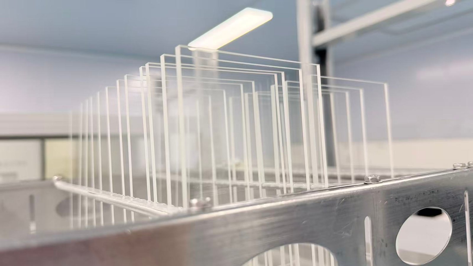
B270 process experience, without invented results
LIGHTING GLASS has experience processing customer-specified B 270. The work may include cutting, edge grinding, chamfering, grinding, polishing, cleaning, inspection and packaging, selected against the approved drawing rather than a generic equipment list.
Customer-specific dimensions, inspection results and part photographs are not disclosed here; none are presented as verified project outcomes.
For an efficient review, submit the drawing with tolerances and surface requirements; identify B 270 or B 270 Thin and thickness; give outline, critical dimensions, chip and chamfer limits, quantity and lead time; state any strengthening, coating and packaging requirements.
Engineering review starts with feasibility of outline, holes and edges, then assigns cutting, grinding, polishing and cleaning steps. A sample or first article should validate the critical requirements before a production schedule is confirmed.
A complete proposal should define the process route, critical control points and gauges, first-article inspection, and protection at delivery. Measured results and inspection records belong to the specific approved project.
Material sets the ceiling; process control sets the floor.
Need Precision Processing for B270 Glass?
Send your drawing, dimensions, tolerances and quantity for a fabrication review.
Email: jerry-ton@lightingglass.cn
Phone / WeChat: +86 13539645045
Website: glassubstrate.net